Title: Semiconductor manufacturing processes
Objective: To have a certain foundation for the overall manufacturing process, and to facilitate the subdivision study of each process.
Text: At present, the most commonly used semiconductor material is silicon Si, from silicon sand, many processes.
The semiconductor manufacturing process can be divided into eight steps, including wafer processing, oxidation, lithography, etching, thin film deposition, interconnection, testing, and packaging.
Step 1: Wafer processing
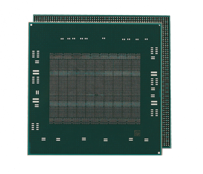
- What is a wafer?
- The wafer Wafer is a circular wafer made of a single crystal column made of silicon Si or gallium arsenide GaAs
- How is the wafer prepared?
- Source of silicon ingot: heat the silica sand, separate carbon monoxide and silicon, repeatedly obtain the ultra-high purity electronic grade silicon EG-Si, and then pull the silicon ingot (monocrystalline silicon column)
- Cut Wafer: the diameter of the silicon ingot determines the diameter of Wafer, and 12 inches (300mm), 8 inches (200mm), 6 inches (150mm) refers to the diameter of the wafer, currently vigorously developing 18 inches (450mm) Wafer, the larger the diameter, the larger the size, can be cut into more chip units, improve the product yield.
- Wafer surface polishing: by cutting the wafer sheet, called “bare” can not directly carry the printed circuit graphics, need to be grinding, chemical etching process to remove surface defects, polishing travel smooth surface, clean and remove residual contaminants to get the surface clean finished wafer.
Step 2: Oxidation
- Why the oxidation?
- Travel protective film on the surface of Wafer, so that it is not affected by chemical impurities, avoid leakage current into the circuit, prevent diffusion during ion implantation and slippage during etching. The thickness of the oxide layer needs to be considered.
- detailed procedures
- Remove impurities and pollutants, including organic matter, metal and other impurities and evaporation of residual water.
- Thermal oxidation travel protective film (SiO2): 800-1200℃, with oxygen or steam through the surface
- Dry oxidation: pure O2, slow speed, thin oxide layer, dense
- Wet oxidation: to use both oxygen and high solubility of water vapor, fast growth rate, slow oxide layer speed, low density
Step 3: lithography
The circuit pattern is printed on Wafer by light. The finer the circuit pattern, the higher the integration of the finished chip
- Cover with photoresist
- Using rotary coating method, the thinner the photoresist layer, the more uniform the coating, the main use is positive glue
- Positive glue: decompose by light, leaving an area without light
- Negative glue: the pattern of the light-receiving part appears
- Mask
- The mask is used to protect certain areas from etched material, by covering the mask in areas that do not require etched, ensures that only exposed areas are etched.
- The mask contains the circuit diagram, the light through the mask, through the lens focus, shrink, realize printing the circuit on the photoresist.
- Exposure
- Control the light exposure, complete the circuit printing, the more er the printing pattern, the completed chip can accommodate more components, help to improve the production efficiency, reduce the production cost of a single element
- The development
- Spray the developer solution to remove the photoresist of the uncovered part of the pattern, so that the printed pattern can appear, and ensure the quality of the measuring equipment and light mirror to detect the circuit diagram.
Step 4: Eclipse
Remove the excess oxide film, leaving the semiconductor circuit diagram
- Wet etching
- Using chemical solvent has the advantages of low cost, fast speed and high production efficiency; disadvantages: it is isotropic, which causes mask with etched oxide film and is difficult to handle very fine circuit diagram.
- Dry etching (gas or plasma)
- Chemical etching: eg.HF gases are isotropic and are not suitable for fine etching
- Physical sputtering: plasma impact removes excess oxide layer, anisotropy (at different horizontal, vertical etching speed) with higher precision and slower speed.
- Reaction ion etching RIE: using plasma for ionization physical etching, at the same time with the help of plasma activation generated free radical etching, fast, anisotropy, higher precision
Step 5: Film deposition
Film thickness is less than 1um and deposition is in molecules or atoms (dry and wet deposition)
- definition
- To form a multi-layer semiconductor structure, the device stack (the multi-layer thin metal film and the dielectric film, namely the conductive film and the insulating film) is first manufactured to form a three-dimensional structure after removing the excess part by repeated etching
- Chemical vapor deposition CVD:
- The precursor is chemically reacted in the reaction cavity to form a thin film attached to the surface of the wafer. Including plasma chemical vapor deposition, with the help of plasma reaction, reduce the reaction temperature, reduce the deposition speed, to get a higher quality of the film.
- Atomic layer deposition ALD:
- Several atomic layers are deposited at a time to form a thin film (first coating the precursor and introducing different gases into the substances needed to react with the precursor)
- Physical vapor deposition PVD:
- By eg sputtering, through the argon plasma bombardment, the target atomic body is sputtered and deposited on the wafer surface to form a film. In certain cases, the deposited film can be treated and modified by ultraviolet heat treatment (UVTP) and other technologies.
Step 6: Interconnection
- Definition:
- Based on the lithography, etching, deposition process component transistor components, different semiconductor components (transistors, capacitors, resistors) are further connected through the interconnection process to form a complete circuit to realize the transmission and reception of power and signals. It is suitable for the interconnection of conductive metals (requiring low resistivity, thermochemical stability, high reliability, and low manufacturing cost).
- Aluminum interconnection process:
- Usually includes aluminum deposition, lithography, etching, annealing and other steps. First, a layer of aluminum film is deposited on the silicon wafer, and the interconnection pattern is defined by lithography technology, then applying etching technology to remove excess aluminum, and finally improve the contact characteristics of aluminum and silicon by annealing treatment
- Advantages: good aluminum electrical conductivity, simple process, low cost.
- Disadvantages: there are limitations, the contact resistance of aluminum and silicon is high, aluminum is easy to react with silicon, leading to the reliability of the interconnect layer.
- Copper interconnection technology
- With higher conductivity and resistivity, more suitable for interconnection than aluminum; copper interconnection process is more complex (including copper deposition, lithography, etching, chemical mechanical polishing CMP), usually using double inlay technology (Damascene), now wafer grooves and holes, then fill with copper, and finally removal of excess copper by CMP to form a flat surface.
- Advantages: with lower resistance and higher current bearing capacity, can reduce the power consumption of interconnection, improve the performance of the chip, the electrical mobility of copper is low, is conducive to improve the reliability of interconnection.
- Disadvantages: complex process, high cost, copper and silicon reaction is strong, need special materials to block, prevent copper from spreading into silicon.
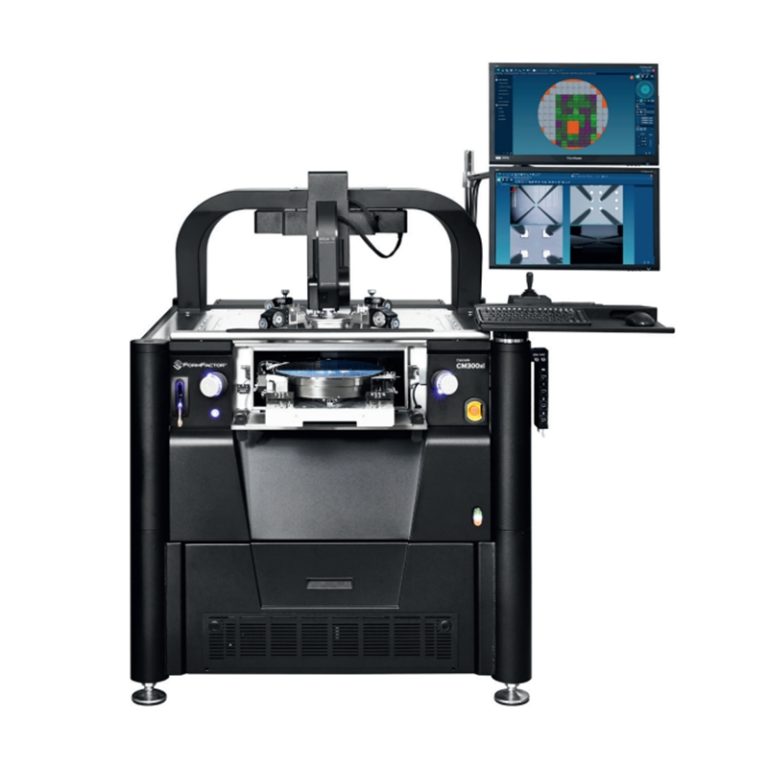
Step 7: Test
- Definition
- Test whether the semiconductor chip reaches a certain quality, eliminate bad products and improve reliability
- Score sorting EDS:
To detect the electrical performance of each chip in the wafer state and improve the semiconductor yield.
- Electrical parameter monitoring EPM: Test every device (transistors, capacitor, diode) required for the semiconductor integrated circuit to ensure that the parameters reach the standard, not to detect bad products. The main action type provides the electrical characteristic data to improve the manufacturing process efficiency and product performance.
- Wafer aging test: Place the wafer at AC / DC voltage to test the product that may defect early (improve final reliability by detecting potential defects); failure rate (ratio from manufacturing defects, ratio of defects for the entire life cycle of the product)
- Detection: Connect the semiconductor chip to the test device with a probe card for temperature, speed and motion detection to detect related semiconductor functions; the high and low temperature test requirements of the memory semiconductor are 80 to 90℃ and-5 to 40℃, respectively
- Repair: some defective products can be repaired, and the defective components can be replaced
Step 8: Packaging
- Definition:
- After the previous process, a single chip is processed, and a separate chip should be cut. At this time, the chip is fragile and cannot exchange electrical signals, so it needs to be processed separately to form a protective shell outside the chip, so that it can exchange electrical signals with the outside.
- Wafer saw cutting: First, grind the back of the wafer so that its thickness can meet the packaging requirements. Cut the slice line along the wafer and know that the semiconductor chip is separated.
- Blade cutting: diamond blade, more likely to produce friction heat and debris, damage to the wafer
- Laser cutting: higher accuracy, used for processing thin thickness, small line spacing wafer
- Plasma cutting: using plasma etching
- Single wafer attachment:
- After the chip is separated from the wafer, it needs to be attached to the lead frame of the base; the base: protect the semiconductor chip to exchange electrical signals with the external circuit.
- interconnection
- After the chip is attached to the substrate, it needs to connect the two contact points to realize the electrical signal exchange.
- Lead bonding using a thin gold wire
- Use inverted chip bonding with spherical blocks or tin blocks
- Forming
- Packaging to the outside of the chip protects the semiconductor integrated circuit from temperature and humidity, and the packaging mold is made according to the need, and the chip and epoxy mold plastic are put into the mold for sealing
- Test:
- Conduct electrical, functional and speed tests under different conditions (eg, voltage, temperature, humidity, etc.) to find defects and improve product quality